READY TO DRAW YOUR PLAN?
DO I NEED TO PROVIDE A SET OF PLANS?
Fluid require a set of plans to complete the approval of all building projects.
If your kit patio, carport or shed (class 10) is supplied with structural plans and a Form 15 Engineering Certificate included, you are in luck.
You will simply need to draw a site plan yourself to be complete. Please see here for more details.
If your project is a renovation or an extension you will require a complete set of drafted plans. It is best for these to be created by a building professional (i.e. a draughtsman, builder, architect, building designer or engineer). Please see here for an example of the plans Fluid need.
CARPORTS, PATIOS & SHEDS
Typical Class 10 structures are non-habitable building or structures such as a private garage, carport, shed or the like.
Fluid require the structual plans and a Form 15 Engineering Certificate that come supplied, or on request, from your carport/ patio/ shed supplier. In addition, we require a drawn site plan showing where your structure will go AND an elevation to show the height of your structure.
See instructions below on how to draw a site plan and download an example site plan.
HOW TO DRAW A SITE PLAN – CLASS 10
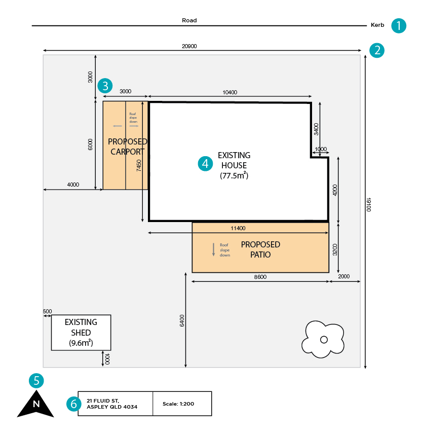
The adjacent diagram is a typical site plan for a proposed carport and patio.
Site plans enable the Fluid team to see where the proposed structure will be constructed on the property, and to ensure it complies with building codes and regulations.
Please ensure the building plans you provide are:
Location of street
Dimensions of all property boundaries (length and width)
Dimensions of existing and proposed structures and distances between structures
Structures labelled
North point
Property details (address etc.)
To assist you with the plan, the location of your house on your block of land may be available from council archives.

HOW TO DRAW A SITE PLAN – CLASS 10
The adjacent diagram is a typical site plan for a proposed carport and patio.
Site plans enable the Fluid team to see where the proposed structure will be constructed on the property, and to ensure it complies with building codes and regulations.
Please ensure the building plans you provide are:
Location of street
Dimensions of all property boundaries (length and width)
Dimensions of existing and proposed structures and distances between structures
Structures labelled
North point
Property details (address etc.)
To assist you with the plan, the location of your house on your block of land may be available from council archives.
HOW TO DRAW AN ELEVATION – CLASS 10
The plan below is a typical elevation drawing showing the proposed carport from the south elevation.
Elevations provide our certifers with a better understanding on what the the existing and proposed structures will look like, and how they are associated with each other.
When drawing an elevation, it is important to show anything that cannot be determined through a floor plan – such as ceiling clearances, stair heights and window and door heights.
Please ensure the elevations you provide have:
- Plan to dimension overall and head clearance
- Demonstrate existing and proposed work (if applicable)
- Location of stairs (if applicable)
- Direction of elevation
RENOVATIONS & EXTENSIONS
Renovations and extensions require more information than Class 10 structures.
Because of this, Fluid require a complete set of drafted plans to complete the approval, including two floor plans (proposed and existing), elevations, sections, roof plan and electrical plan*.
Read the sections below to learn how to draw simple plans, or download our example set of drawings.
*Please note other plans may be required on request depending on the project
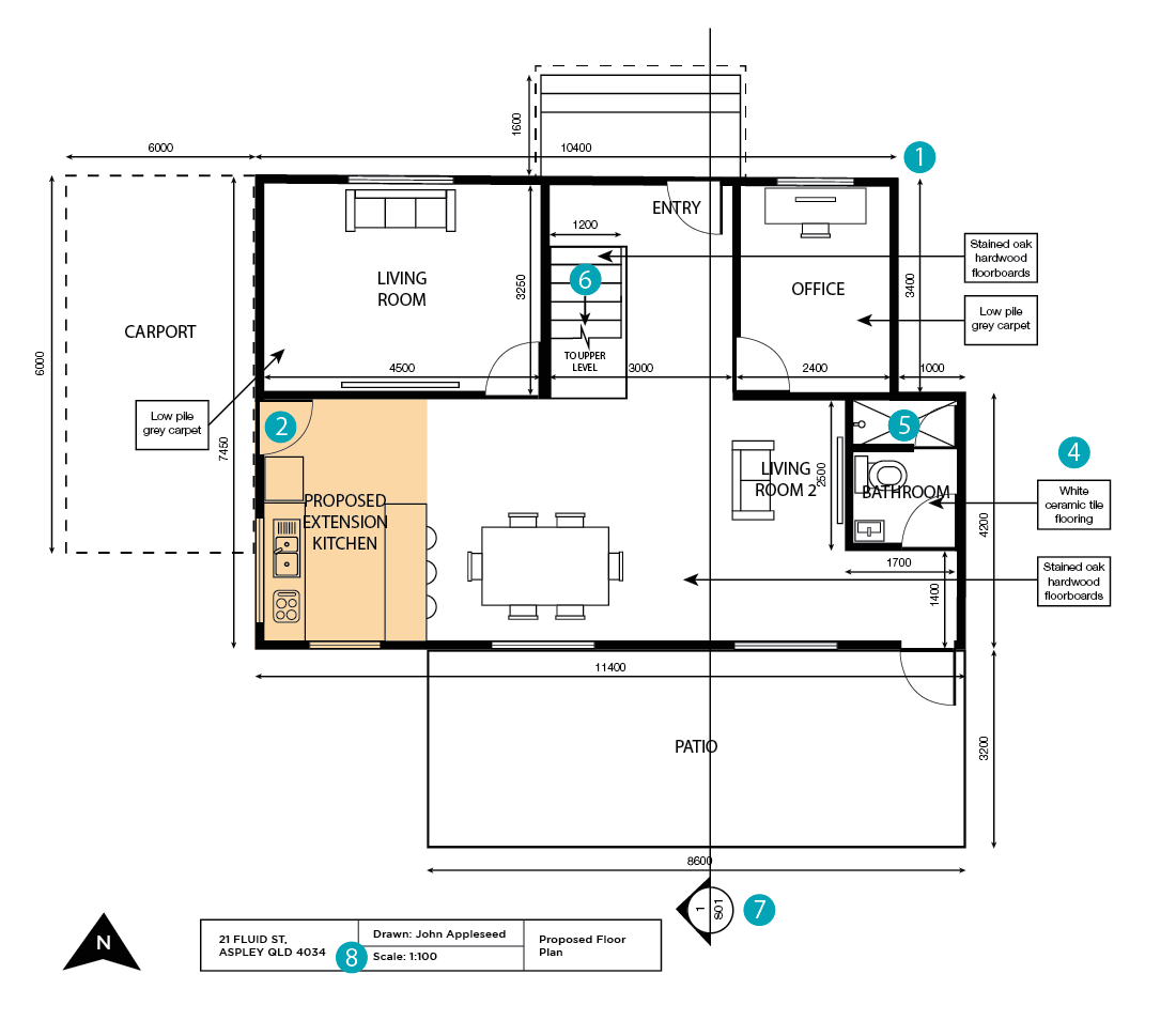
HOW TO DRAW A FLOOR PLAN – RENOVATIONS & EXTENSIONS (PROPOSED)
The adjacent diagram is a typical floor plan (ground floor), showing the location of the proposed kitchen extension.
Floor plans are required if your project is a home extension or renovation, where it allows us to understand where the proposed works will be located and how it associates with the adjoining spaces.
Please ensure the floor plans you provide have:
- Fully dimensioned plan showing length and width
- Location of windows/doors etc.
- Name and use of room
- Floor finishes (carpet, concrete, tiles etc.)
- Location of cupboards, sinks, showers etc. in particular rooms
- Location of stairs
- Location of section plan
- Scale
Note: a floor plan is not always required for all building approvals (i.e. sheds, patio or carports).
HOW TO DRAW A FLOOR PLAN – RENOVATIONS & EXTENSIONS (EXISTING)
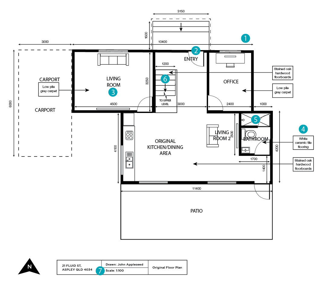
The adjacent diagram is a typical floor plan (ground floor), showing the spaces of the existing home (i.e. what the house looked like before the proposed extension).
Please ensure the floor plans you provide have:
- Fully dimensioned plan showing heights/length etc.
- Plan to dimension overall and head clearance
- Location of windows and doors
- Demonstrate existing and proposed work if applicable
- Location of stairs etc.
- Scale
- Elevation plans to be provided for all elevations (North, South, East and West)
HOW TO DRAW A FLOOR PLAN – RENOVATIONS & EXTENSIONS (EXISTING)
The adjacent diagram is a typical floor plan (ground floor), showing the spaces of the existing home (i.e. what the house looked like before the proposed extension).
Please ensure the floor plans you provide have:
- Fully dimensioned plan showing heights/length etc.
- Plan to dimension overall and head clearance
- Location of windows and doors
- Demonstrate existing and proposed work if applicable
- Location of stairs etc.
- Scale
- Elevation plans to be provided for all elevations (North, South, East and West)
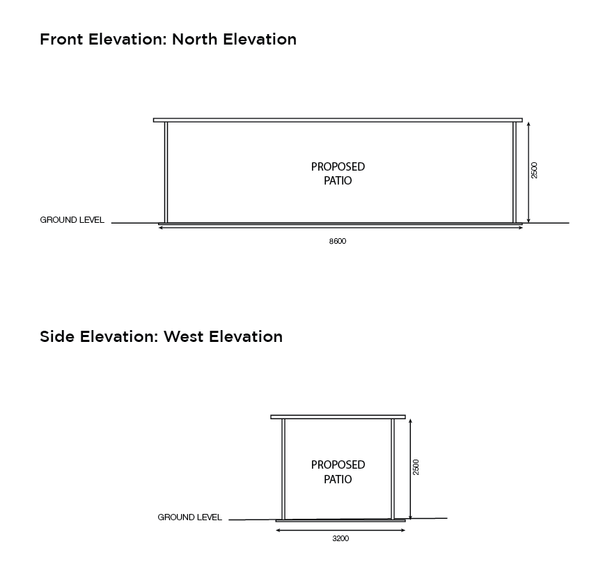
HOW TO DRAW AN ELEVATION – RENOVATIONS & EXTENSIONS
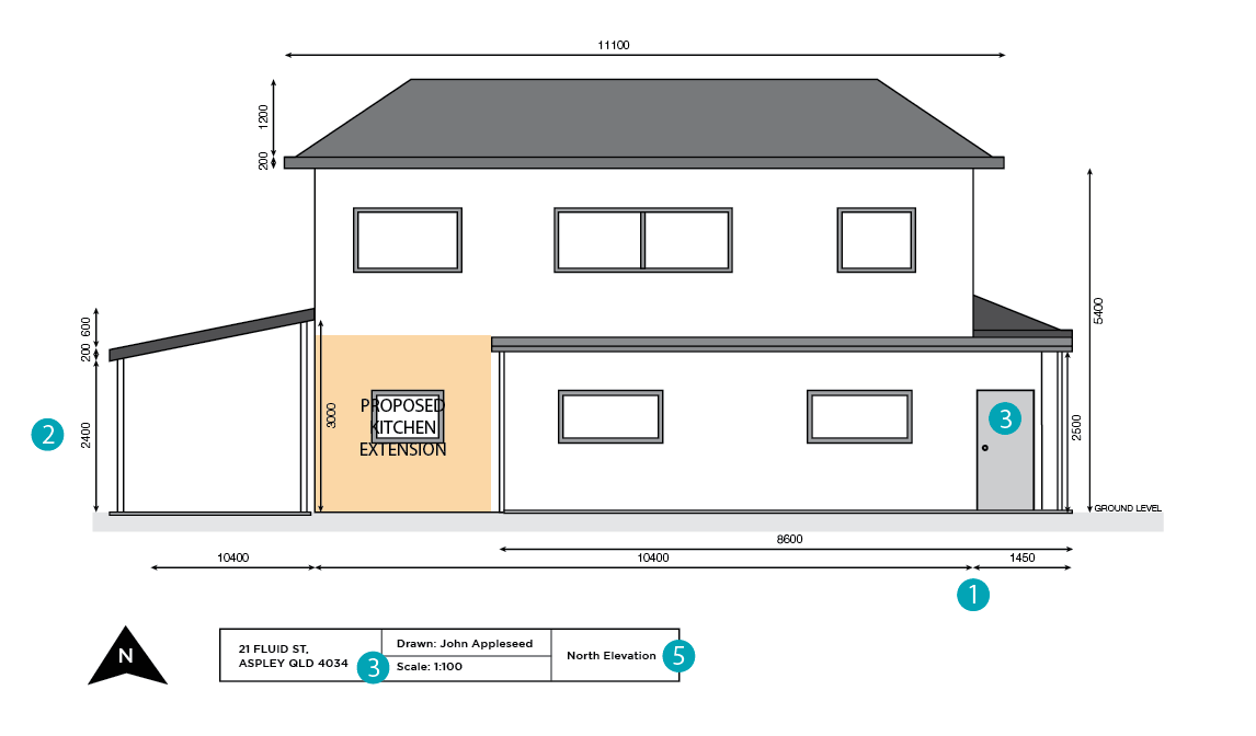
The adjacent diagram is a typical elevation showing the kitchen extension from the north elevation.
Elevations provide our certifiers with a better understanding about the existing exterior, what the proposed project will look like and how it fits with other surrounding structures (eg. carports, patios etc.).
Please ensure the elevations you provide have:
- Fully dimensioned plan showing heights/sub floor clearances
- Plan to dimension overall and head clearance
- Location of windows/doors
- Scale
- Elevation plans to be provided for all elevations (North, South, East & West)
HOW TO DRAW AN ELEVATION – RENOVATIONS & EXTENSIONS
The adjacent diagram is a typical elevation showing the kitchen extension from the north elevation.
Elevations provide our certifiers with a better understanding about the existing exterior, what the proposed project will look like and how it fits with other surrounding structures (eg. carports, patios etc.).
Please ensure the elevations you provide have:
- Fully dimensioned plan showing heights/sub floor clearances
- Plan to dimension overall and head clearance
- Location of windows/doors
- Scale
- Elevation plans to be provided for all elevations (North, South, East & West)
HOW TO DRAW A SECTION –
RENOVATIONS & EXTENSIONS (EXISTING)
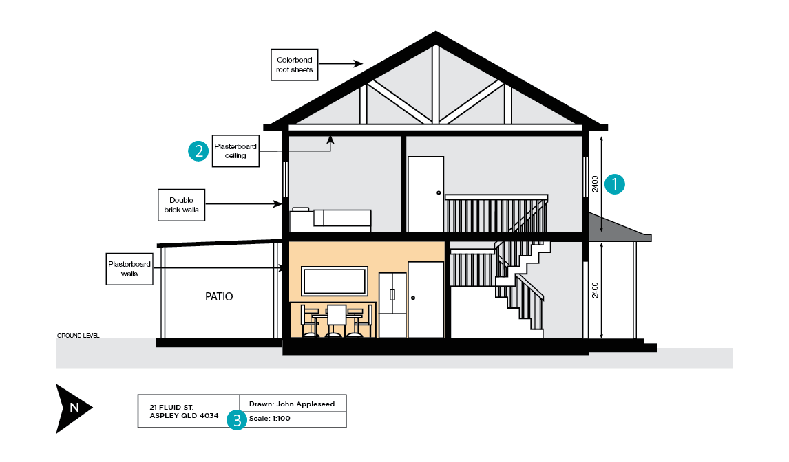
The adjacent diagram is a typical section showing the interior spaces of the home.
Sections provide our certifiers with a better understanding on what the extension will look like from the inside of the house, and how it fits in with its surrounding structures.
Please ensure the floor plans you provide have:
- Fully dimensioned plan showing heights/sub floor clearances etc.
- Method of construction for walls/ceiling/roof etc.
- Scale
HOW TO DRAW A SECTION –
RENOVATIONS & EXTENSIONS (EXISTING)
The adjacent diagram is a typical section showing the interior spaces of the home.
Sections provide our certifiers with a better understanding on what the extension will look like from the inside of the house, and how it fits in with its surrounding structures.
Please ensure the floor plans you provide have:
- Fully dimensioned plan showing heights/sub floor clearances etc.
- Method of construction for walls/ceiling/roof etc.
- Scale
HOW TO DRAW AN ELECTRICAL PLAN – RENOVATIONS & EXTENSIONS
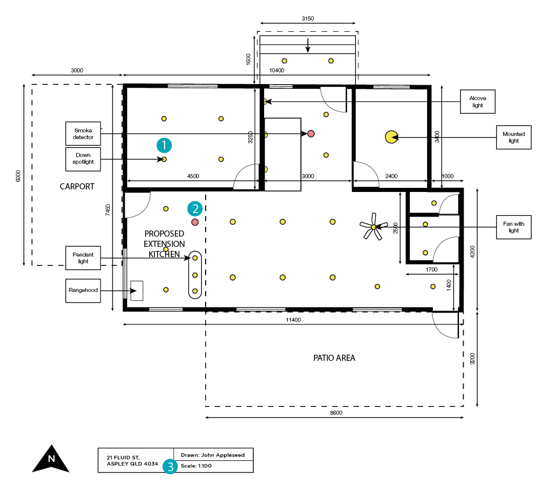
The adjacent diagram is a typical elevation showing the location of installed electricals on the ceiling.
This is not required for all building approvals, however we may request one should your extension/renovation require electrical work.
Electrical plans will show:
- Location of lights and fans etc.
- Location of smoke alarms
- Scale
HOW TO DRAW AN ELECTRICAL PLAN – RENOVATIONS & EXTENSIONS
The adjacent diagram is a typical elevation showing the location of installed electricals on the ceiling.
This is not required for all building approvals, however we may request one should your extension/renovation require electrical work.
Electrical plans will show:
- Location of lights and fans etc.
- Location of smoke alarms
- Scale
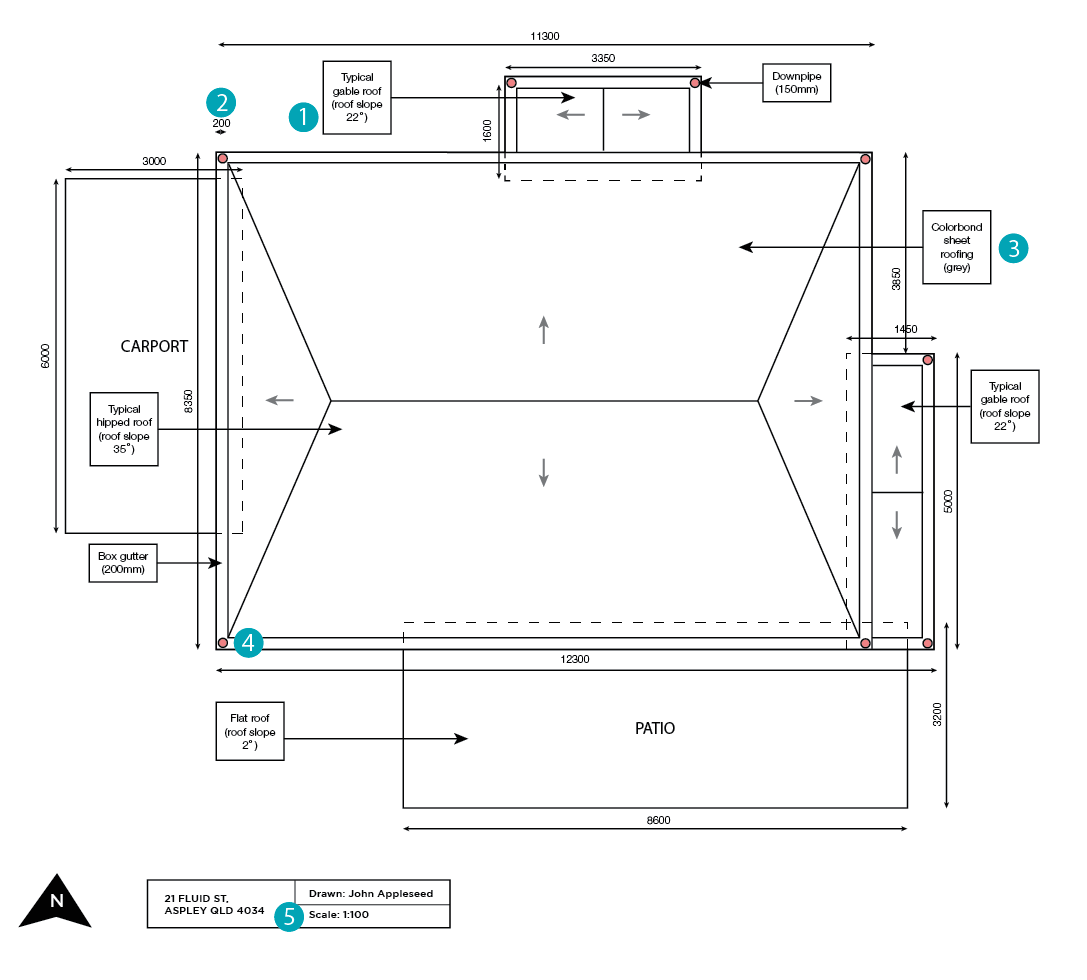
HOW TO DRAW A ROOF PLAN – RENOVATIONS & EXTENSIONS
The adjacent diagram is a typical roof plan which shows the roof details of the existing and proposed structure.
This may not be required for all building approvals, however may be required for structures which are connected or close to the existing structures’ roof.
Please ensure the floor plans you provide have:
- Degree pitch of roof
- Gutter size
- Proposed materials
- Downpipe size and location
- Scale